Electro-Magnetic Compatibility Testing
What is It?
Electro-Magnetic Compatibility (EMC) testing to verify if a device is emitting large amounts of electro-magnetic radiation, which can be potentially harmful to other equipment, and if it is susceptible to electromagnetic radiation emitted nearby.
Equipment Involved
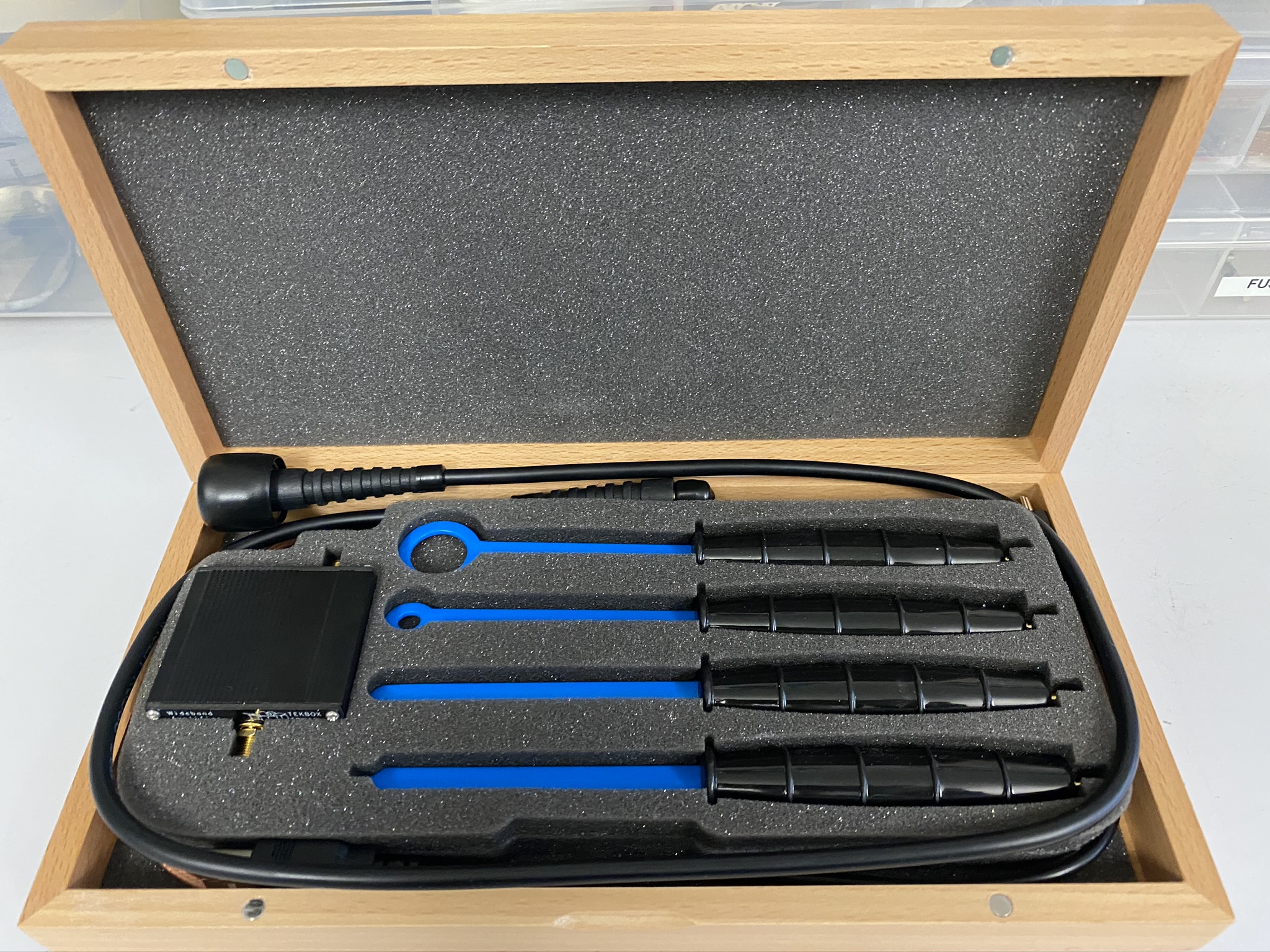
The TBPS01 EMC near field probes H20, H10, H5 and E5 are magnetic field (H) and electric field (E) probes for radiated emissions EMC pre-compliance measurements. The probes are used in the near field of sources of electromagnetic radiation. They serve to locate and identify potential sources of interference within the building blocks of electronic assemblies. The probes act similar as wide bandwidth antennas, picking up radiated emissions from components, PCB traces, housing openings or gaps and from any other parts that could be emitting RF. The probes are usually connected to a spectrum analyzer. Scanning the probe over the surface of a PCB assembly or housing quickly identifies locations which emit electromagnetic radiation. By changing to a probe with smaller size, the origination of the emissions can be further narrowed down. The TBWA2/20dB wideband amplifier is connected between EMC probe and Spectrum Analyzer to increase the dynamic range of the measurements.
A large probe will be able to detect radiation easier, however it will be difficult to decern what the source of the radiation is. Smaller probes allow you to tell which component of the device is emitting the radiation but will be more difficult to detect the radiation initially. The probes can be swapped mid-way through, detecting an initial signal with the larger probe, and then narrowing in on the source with the smaller probe. The smallest probe is a E-field probe and is used to detect electric field as opposed to the magnetic field for the 3 other larger probes.
Methodology
Test 1: Radiation test- Choose the appropriate probe from the tekbox probe set.
- Connect the probe to the amplifier and connect the amplifier to the spectrum analyser.
- Configure the spectrum analyser to show the frequency range of interest or alternately show the entire frequency range of the analyser.
- Place the probes near the device without touching any electrical components (The probes are electrically insulated, however if this insulation becomes damaged there can be a risk of electrical shock)
- Read radiation detected from the spectrum analyser
Test 2: Immunity test
For this test you plug the probes into an RF generator to produce a RF field. The probes are then placed near the device. Changes to the operation of the device must then be monitored. Changes such as the device switching off, changing states, loss of memory, etc. If none of these occur, then the device passes. Failing one or more of these does not mean the device automatically fails. Depending on the standard used as long as the device has no permanent damage or loss of data then the device will normally pass with just a lower grade
Warning: Some frequencies are illegal to be emitted. Before completing this test please check if the frequency being used is allowed. If not, then the test must be performed in an electrically shielded room.
Limitations
The standards for EMC testing are all defined in the far-field. The probes we have are near-field probes and hence we cannot measure the far field radiation. Additionally, there is no way to convert between far field and near field. The test we do will indicate which components are emitting large amounts of radiation, but we will not be able to determine if a device complies with a specific standard or not.

Connect With Us?
We have a proven track record of designing testing equipment and tests. By sharing our highly developed systems and processes with innovators we’re perfectly placed to support WA-based businesses.